| Pipe Size (NPS) | A | B | C | Approx. Weight (lb) | |
|---|---|---|---|---|---|
| STD | XS | ||||
| 1/2 | – | – | – | – | – |
| 3/4 | – | – | – | – | – |
| 1 | – | – | – | – | – |
| 1 1/4 | – | – | – | – | – |
| 1 1/2 | – | – | – | – | – |
| 2 | 3 1/2 | 1/2 | 3 | 1.8 | 2.5 |
| 2 1/2 | 4 3/8 | 5/8 | 3 3/4 | 3.8 | 5.0 |
| 3 | 5 1/4 | 3/4 | 4 1/2 | 5.8 | 8.0 |
| 3 1/2 | 6 1/8 | 7/8 | 5 1/4 | 7.7 | 11.0 |
| 4 | 7 | 1 | 6 | 11.0 | 15.0 |
| 5 | 8 3/4 | 1 1/4 | 7 1/2 | 17.0 | 25.0 |
| 6 | 10 1/2 | 1 1/2 | 9 | 29.0 | 45.0 |
| 8 | 14 | 2 | 12 | 55.0 | 85.0 |
| 10 | 17 1/2 | 2 1/2 | 15 | 95.0 | 130.0 |
| 12 | 21 | 3 | 18 | 146.0 | 195.0 |
| 14 | 24 1/2 | 3 1/2 | 21 | 185.0 | 245.0 |
| 16 | 28 | 4 | 24 | 246.0 | 329.0 |
| 18 | 31 1/2 | 4 1/2 | 27 | 316.0 | 420.0 |
| 20 | 35 | 5 | 30 | 400.0 | 475.0 |
| 22 | 38 1/2 | 5 1/2 | 33 | 468.0 | 625.0 |
| 24 | 42 | 6 | 36 | 571.0 | 750.0 |
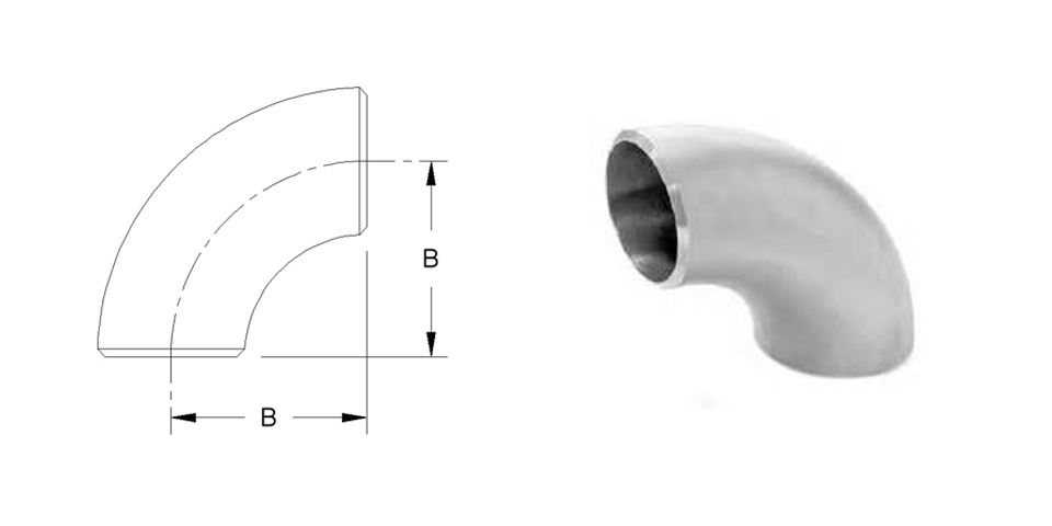
- Dimensions per ANSI/ASME B16.9.
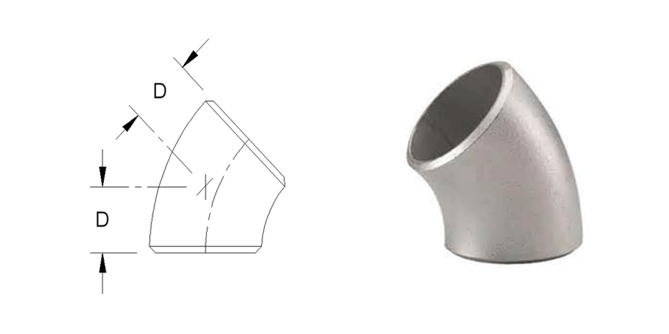
- A 90° elbow long tangent is a long radius (LR) with the centerline curvature equal to 1-1/2 times the nominal pipe size (NPS) and a straight extension at both ends (long tangent) for 2 inch and larger sizes. Tangent elbows provide a straight length at the end to accept a Slip-on Flange. The tangent end for the flange is not beveled.