Showing posts with tag: tees
Jan 18, 2018
by
PipeAdmin
Tags:
AWWA ,
base ,
C110 ,
Charts ,
Ductile Iron ,
Flanged bends ,
Gray-Iron ,
Imperial ,
inches ,
Pipe Fittings ,
tees
Jan 17, 2018
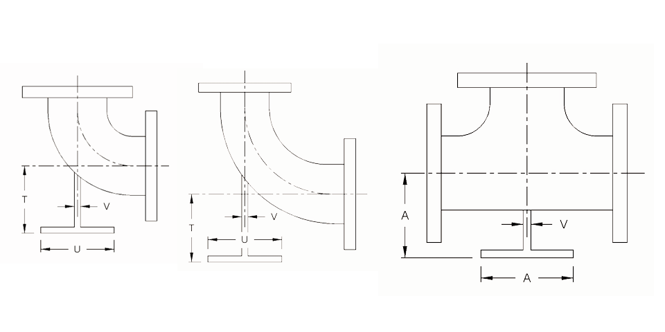
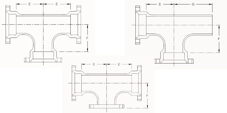
Pipe Size Dimensions (in) Approx. Weight (lb) MJ
RUN (E)
Branch (F)
RUN (G)
* 2x2x2
3.25
3.25
–
21
* 3x3x2
3.25
3.25
–
45
3x3x3
5.5
5.5
13.5
58
* 4x4x2
4.8
4.8
14.5
68
4x4x3
6.5
6.5
14.5
77
4x4x4
6.5
6.5
14.5
78
4x4x6
8
8
–
112
* 6x6x2
8
8
–
78
6x6x3
8
8
16
112
6x6x4
8
8
16
110
6x6x6
8
8
16
119
6x6x8
9
9
–
158
8x8x3
9
9
17
155
8x8x4
9
9
17
157
8x8x6
9
9
17
175
8x8x8
9
9
17
199
10x10x4
11
11
19
–
10x10x6
11
11
19
258
10x10x8
11
11
19
268
10x10x10
11
11
19
300
12x12x4
12
12
20
318
12x12x6
12
12
20
325
12x12x8
12
12
20
335
12x12x10
12
12
20
392
12x12x12
12
12
20
396
14x14x12
14
14
22
540
14x14x14
14
14
22
585
* 16x16x4
15
15
23
600
16x16x6
15
15
23
615
16x16x8
15
15
23
625
16x16x10
15
15
23
645
16x16x12
15
15
23
660
16x16x16
15
15
23
740
18x18x6
13
15.5
–
710
18x18x8
13
15.5
–
674
18x18x12
13
15.5
–
749
18x18x18
16.5
16.5
–
945
20x20x6
14
17
–
849
20x20x8
14
17
–
892
20x20x12
14
17
–
896
20x20x16
18
18
–
1095
20x20x20
18
18
–
1258
24x24x6
15
19
–
1233
24x24x8
15
19
–
1234
24x24x12
15
19
–
1256
24x24x14
15
19
–
1220
24x24x16
15
19
–
1245
24x24x18
22
22
–
1735
24x24x20
22
22
–
1720
24x24x24
22
22
–
1947
30x30x6
18
23
–
2050
30x30x8
18
23
–
2060
30x30x10
18
23
–
2075
30x30x12
18
23
–
2090
30x30x16
18
23
–
2145
30x30x18
18
23
–
2170
30x30x20
18
23
–
2205
30x30x24
25
25
–
2880
30x30x30
25
25
–
2275
36x36x6
20
26
–
2439
36x36x8
20
26
–
2444
36x36x10
20
26
–
2535
36x36x12
20
26
–
2541
36x36x14
20
26
–
2570
36x36x16
20
26
–
2585
36x36x18
20
26
–
2610
36x36x20
20
26
–
2635
36x36x24
20
26
–
2792
36x36x30
28
28
–
3545
36x36x36
28
28
–
3450
42x42x24
23
30
–
3690
42x42x30
31
31
–
4650
42x42x36
31
31
–
4880
42x42x42
31
31
–
6320
48x48x24
26
34
–
4995
48x48x30
26
34
–
5140
48x48x36
34
34
–
6280
48x48x42
34
34
–
8130
48x48x48
34
34
–
8420
* These fittings are not included in AWWA C110/A21.10 For flange dimensions see Flange – ANSI Class 125, C110, DI
AWWA C110/A21.10 – Ductile-Iron and Gray-Iron Fittings (3″ to 48″)
ASME B16.1 – Gray Iron Pipe Flanges and Flanged Fittings: Classes 25, 125, and 250 (Flange surfaces shall be faced and drilled in accordance with ANSI Class 125)
AWWA C104/A21.4 – Standard for Cement-Mortar Lining for Ductile-Iron Pipe and Fittings for Water
AWWA C111/A21.11 – Rubber-Gasket Joints for Ductile-Iron Pressure Pipe and Fittings
Ductile iron mechanical joint fittings 3″ through 24″ shall be rated for 350 PSI working pressure.
Flanged ductile iron fittings in 24 inch and smaller sizes may be rated for 350 psi with the use of special gaskets.
MJ – mechanical joint
PE – plain end
FLG – flange