Showing posts with tag: Pipe Fittings

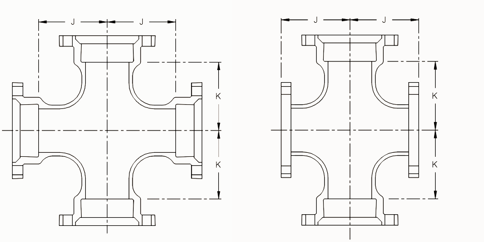
Mechanical Joint Crosses – Full Body, AWWA C110, DI (in)

Pipe SizeDimensions (in)Approx. Weight (lb)
RunBranchJKMJ*  MJ x FLG
6 6 8.0 8.0 160 141
8 4 9.0 9.0 185 –
8 6 9.0 9.0 205 182
8 8 9.0 9.0 255 245
10 6 11.0 10.0 285 –
10 8 11.0 11.0 310 –
10 10 11.0 11.0 380 360
12 6 12.0 12.0 361 367
12 8 12.0 12.0 371 373
12 12 12.0 12.0 486 487
14 8 14.0 14.0 550 –
14 14 14.0 14.0 779 –
16 6 15.0 15.0 650 –
16 8 15.0 15.0 675 655
16 16 15.0 15.0 895 875
18 8 13.0 15.5 775 –
18 10 13.0 15.5 760 –
18 12 13.0 15.5 860 –
18 18 16.5 16.5 1140 –
20 8 14.0 17.0 951 –
20 12 14.0 17.0 977 –
20 16 18.0 18.0 1245 –
20 20 18.0 18.0 1440 –
24 8 15.0 19.0 1244 –
24 12 15.0 19.0 1326 –
24 16 15.0 19.0 1479 –
24 20 22.0 22.0 1965 –
24 24 22.0 22.0 2192 –
30 6 18.0 23.0 2085 –
30 12 18.0 23.0 2165 –
30 24 25.0 25.0 3180 –
30 30 25.0 25.0 3640 –
36 24 20.0 26.0 2910 –
36 36 28.0 28.0 4370 –
42 42 31.0 31.0 7145 –
48 24 26.0 34.0 5210 –
48 36 34.0 34.0 6790 –
48 48 34.0 34.0 9380 –
  • *  These fittings are not included in AWWA C110/A21.10
  • For flange dimensions see Flange – ANSI Class 125, C110, DI
  • AWWA C110/A21.10 – Ductile-Iron and Gray-Iron Fittings (3″ to 48″)
  • ASME B16.1 – Gray Iron Pipe Flanges and Flanged Fittings: Classes 25, 125, and 250 (Flange surfaces shall be faced and drilled in accordance with ANSI Class 125)
  • AWWA C104/A21.4 – Standard for Cement-Mortar Lining for Ductile-Iron Pipe and Fittings for Water
  • AWWA C111/A21.11 – Rubber-Gasket Joints for Ductile-Iron Pressure Pipe and Fittings
  • Ductile iron mechanical joint fittings 3″ through 24″ shall be rated for 350 PSI working pressure.
  • Flanged ductile iron fittings in 24 inch and smaller sizes may be rated for 350 psi with the use of special gaskets.
  • MJ – mechanical joint
  • PE – plain end
  • FLG – flange

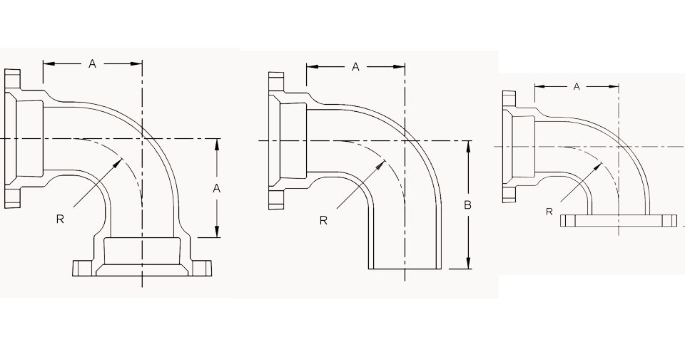
Mechanical Joint 90 Bends – Full Body, AWWA C110, DI (in)

Pipe SizeDimension (in)Approx. Weight (lb)
RABMJ x MJMJ x PEMJ x FLG
*  2 2.25 3.25 – 16 – –
3 4.0 5.5 13.5 26 36 –
4 4.5 6.5 14.5 56 53 51
6 6.0 8.0 16.0 88 80 75
8 7.0 9.0 17.0 123 119 118
10 9.0 11.0 19.0 189 181 168
12 10.0 12.0 20.0 268 252 288
14 11.5 14.0 22.0 380 – –
16 12.5 15.0 23.0 552 470 465
18 14.0 16.5 24.5 625 600 577
20 15.5 18.0 26.0 862 775 –
24 18.5 22.0 30.0 1423 1301 1150
30 21.5 25.0 33.0 1942 1920 –
36 24.5 28.0 36.0 2629 2310 –
42 27.5 31.0 – 3410 – –
48 30.5 34.0 – 4595 – –
  • *  These fittings are not included in AWWA C110/A21.10
  • For flange dimensions see Flange – ANSI Class 125, C110, DI
  • AWWA C110/A21.10 – Ductile-Iron and Gray-Iron Fittings (3″ to 48″)
  • ASME B16.1 – Gray Iron Pipe Flanges and Flanged Fittings: Classes 25, 125, and 250 (Flange surfaces shall be faced and drilled in accordance with ANSI Class 125)
  • AWWA C104/A21.4 – Standard for Cement-Mortar Lining for Ductile-Iron Pipe and Fittings for Water
  • AWWA C111/A21.11 – Rubber-Gasket Joints for Ductile-Iron Pressure Pipe and Fittings
  • Ductile iron mechanical joint fittings 3″ through 24″ shall be rated for 350 PSI working pressure.
  • Flanged ductile iron fittings in 24 inch and smaller sizes may be rated for 350 psi with the use of special gaskets.
  • MJ – mechanical joint
  • PE – plain end
  • FLG – flange

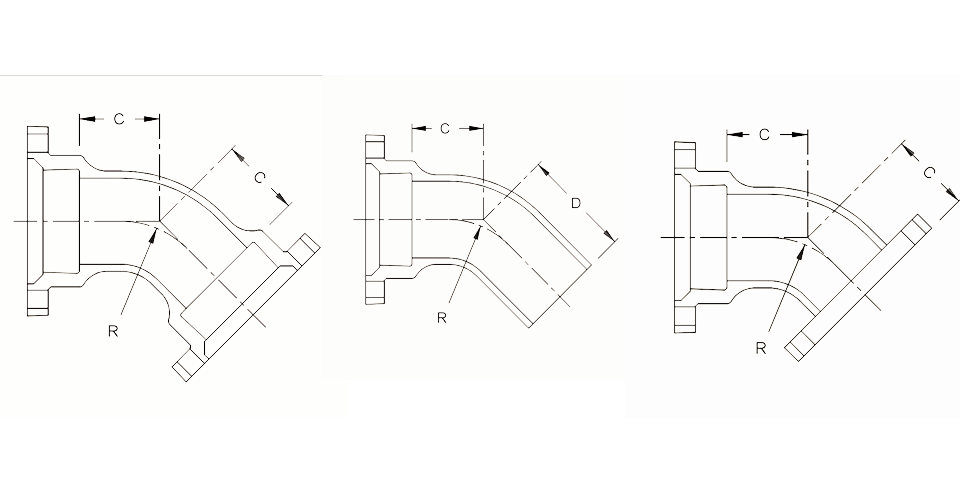
Mechanical Joint 45 Bends – Full Body, AWWA C110, DI (in)

Pipe SizeDimension (in)Approx. Weight (lb)
RCDMJ x MJMJ x PEMJ x FLG
*  2 1.96 1.8 – 16 – –
3 3.62 3.0 11.0 30 – –
4 4.81 4.0 12.0 53 48 45
6 7.25 5.0 13.0 77 60 69
8 8.44 5.5 13.5 110 107 111
10 10.88 6.5 14.5 172 168 167
12 13.25 7.5 15.5 222 215 218
14 12.06 7.5 15.5 311 – –
16 13.25 8.0 16.0 364 360 360
18 14.50 8.5 16.5 531 430 455
20 16.88 9.5 17.5 655 543 664
24 18.12 11.0 19.0 865 1099 825
30 27.75 15.0 23.0 1447 – 1510
36 35.00 18.0 26.0 2435 – 1930
42 42.25 21.0 – 2955 – –
48 49.50 24.0 – 4080 – –
  • *  These fittings are not included in AWWA C110/A21.10
  • For flange dimensions see Flange – ANSI Class 125, C110, DI
  • AWWA C110/A21.10 – Ductile-Iron and Gray-Iron Fittings (3″ to 48″)
  • ASME B16.1 – Gray Iron Pipe Flanges and Flanged Fittings: Classes 25, 125, and 250 (Flange surfaces shall be faced and drilled in accordance with ANSI Class 125)
  • AWWA C104/A21.4 – Standard for Cement-Mortar Lining for Ductile-Iron Pipe and Fittings for Water
  • AWWA C111/A21.11 – Rubber-Gasket Joints for Ductile-Iron Pressure Pipe and Fittings
  • Ductile iron mechanical joint fittings 3″ through 24″ shall be rated for 350 PSI working pressure.
  • Flanged ductile iron fittings in 24 inch and smaller sizes may be rated for 350 psi with the use of special gaskets.
  • MJ – mechanical joint
  • PE – plain end
  • FLG – flange

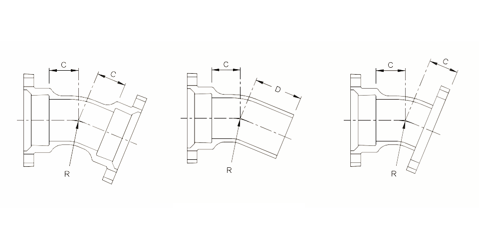
Mechanical Joint 22 1/2 Bends – Full Body, AWWA C110, DI (in)

Pipe SizeDimension (in)Approx. Weight (lb)
RCDMJ x MJMJ x PEMJ x FLG
3 7.56 3.0 11.0 30 – –
4 10.06 4.0 12.0 52 – –
6 15.06 5.0 13.0 77 71 70
8 17.62 5.5 13.5 110 107 109
10 22.62 6.5 14.5 156 155 163
12 27.62 7.5 15.5 221 215 224
14 25.12 7.5 15.5 300 – –
16 27.62 8.0 16.0 391 315 365
18 30.19 8.5 16.5 527 422 455
20 35.19 9.5 17.5 611 – 575
24 37.69 11.0 19.0 986 800 930
30 57.81 15.0 23.0 1898 – 1540
36 72.88 18.0 26.0 2372 – 1970
42 88.00 21.0 – 3020 – –
48 103.06 24.0 – 4170 – –
  • For flange dimensions see Flange – ANSI Class 125, C110, DI
  • AWWA C110/A21.10 – Ductile-Iron and Gray-Iron Fittings (3″ to 48″)
  • ASME B16.1 – Gray Iron Pipe Flanges and Flanged Fittings: Classes 25, 125, and 250 (Flange surfaces shall be faced and drilled in accordance with ANSI Class 125)
  • AWWA C104/A21.4 – Standard for Cement-Mortar Lining for Ductile-Iron Pipe and Fittings for Water
  • AWWA C111/A21.11 – Rubber-Gasket Joints for Ductile-Iron Pressure Pipe and Fittings
  • Ductile iron mechanical joint fittings 3″ through 24″ shall be rated for 350 PSI working pressure.
  • Flanged ductile iron fittings in 24 inch and smaller sizes may be rated for 350 psi with the use of special gaskets.
  • MJ – mechanical joint
  • PE – plain end
  • FLG – flange

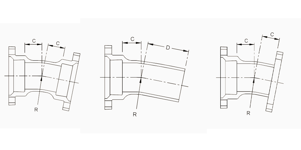
Mechanical Joint 11 1/4 Bends – Full Body, AWWA C110, DI (in)

Pipe SizeDimension (in)Approx. Weight (lb)
RCDMJ x MJMJ x PEMJ x FLG
3 15.25 3.0 11.0 30 – –
4 20.31 4.0 12.0 52 – –
6 30.50 5.0 13.0 65 71 –
8 35.50 5.5 13.5 104 105 –
10 45.69 6.5 14.5 171 – –
12 55.81 7.5 15.5 221 215 –
14 50.75 7.5 15.5 305 – –
16 55.81 8.0 16.0 391 367 –
18 60.94 8.5 16.5 525 422 –
20 71.06 9.5 17.5 605 – –
24 76.12 11.0 19.0 996 800 972
30 116.75 15.0 23.0 1410 – 1305
36 147.25 18.0 26.0 2397 – 2185
42 177.69 21.0 – 3035 – –
48 208.12 24.0 – 4190 – –
  • For flange dimensions see Flange – ANSI Class 125, C110, DI
  • AWWA C110/A21.10 – Ductile-Iron and Gray-Iron Fittings (3″ to 48″)
  • ASME B16.1 – Gray Iron Pipe Flanges and Flanged Fittings: Classes 25, 125, and 250 (Flange surfaces shall be faced and drilled in accordance with ANSI Class 125)
  • AWWA C104/A21.4 – Standard for Cement-Mortar Lining for Ductile-Iron Pipe and Fittings for Water
  • AWWA C111/A21.11 – Rubber-Gasket Joints for Ductile-Iron Pressure Pipe and Fittings
  • Ductile iron mechanical joint fittings 3″ through 24″ shall be rated for 350 PSI working pressure.
  • Flanged ductile iron fittings in 24 inch and smaller sizes may be rated for 350 psi with the use of special gaskets.
  • MJ – mechanical joint
  • PE – plain end
  • FLG – flange

Swage Conc./Ecc.

Pipe Size (NPS)Reduce toLTBDimension A & C
1/81/43/81/23/411-1/41-1/222-1/234681010
1/8 – – 1/4 – – 2-1/2 2-1/2 2-1/2 – – – – – – – – – – – –
1/4 1/8 2-1/4 3/8 2-3/8 2-1/8 – 2-3/8 2-3/8 2-5/8 3-1/8 3-5/8 4-1/2 6-1/8 6-5/8 7-5/8 8-5/8 – – – –
3/8 1/8 to 1/4 2-1/2 3/8 2-3/8 2-1/8 2 – 2-3/8 2-5/8 3-1/8 3-5/8 4-1/2 6-1/8 6-5/8 7-5/8 8-5/8 – – – –
1/2 1/8 to 3/8 2-3/4 1/2 2-1/4 2 1-7/8 – – 2-1/2 3 3-1/2 4 6 6-1/2 7-1/2 8-1/2 11-1/2 – – –
3/4 1/8 to 1/2 3 9/16 2-7/16 – 2-1/16 2-1/16 1-15/16 – 2-15/16 3-7/16 3-15/16 5-15/16 6-7/16 7-7/16 8-7/16 11-7/16 – – –
1 1/8 to 3/4 3-1/2 11/16 2-13/16 – 2-7/16 2-7/16 2-5/16 2-1/16 – 3-5/16 3-13/16 5-13/16 6-5/16 7-5/16 8-5/16 11-5/16 – – –
1 1/4 1/4 to 1 4 11/16 3-5/16 – 2-15/16 2-15/16 2-13/16 2-3/4 2-5/8 – 3-13/16 5-13/16 6-5/16 7-5/16 8-5/16 11-5/16 – – –
1 1/2 1/4 to 1-1/4 4-1/2 11/16 3-13/16 – 3-7/16 3-7/16 3-5/16 3-1/4 3-1/8 3-1/8 – 5-13/16 6-5/16 7-5/16 8-5/16 11-5/16 – – –
2 1/4 to 1-1/2 6-1/2 3/4 5-3/4 – 5-3/8 5-3/8 5-1/4 5-3/16 5-1/16 5-1/16 5-1/16 – 6-1/4 7-1/4 8-1/4 11-1/4 12-1/4 14-1/4 15-1/4
2 1/2 1/4 to 2 7 15/16 6-1/16 – 5-11/16 5-11/16 5-9/16 5-1/2 5-3/8 5-3/8 5-3/8 5-5/16 – 7-1/16 8-1/16 11-1/16 12-1/16 14-1/16 15-1/16
3 1/4 to 2-1/2 8 1 7 – 6-5/8 6-5/8 6-1/2 6-7/16 6-5/16 6-5/16 6-5/16 6-1/4 6-1/16 – 8 11 12 14 15
3 1/2 1/4 to 3 8 1 1/16 – – – – – – – – – – – – – – – – –
4 1/4 to 3-1/2 9 1-1/8 7-7/8 – 7-1/2 7-1/2 7-3/8 7-5/16 7-3/16 7-3/16 7-3/16 7-1/8 6-15/16 6-1/2 – – – – –
5 1/2 to 4 11 – – – – – – – – – – – – – – – – – –
6 1/2 to 5 12 1-5/16 10-11/16 – – – 10-3/16 10-1/2 10 10 10 9-13/16 9-3/4 9-11/16 9-9/16 – 11-11/16 13-11/16 14-11/16
8 2 to 6 13 1-7/16 11-9/16 – – – – – – – – 10-13/16 10-5/8 10-9/16 10-9/16 10-1/4 – 13-9/16 14-9/16
10 2 to 8 15 1-5/8 13-3/8 – – – – – – – – 12-5/8 12-7/8 12-3/8 12-1/4 12-1/16 11-15/16 – 14-3/8
12 2 to 10 16 1-3/4 14-1/2 – – – – – – – – 13-1/2 13-5/16 13-1/4 13-1/8 12-15/16 12-13/16 12-5/8 –
14 2 to 12 17 – – – – – – – – – – – – – – – – – –
16 2 to 14 18 – – – – – – – – – – – – – – – – – –
18 2 to 16 20 – – – – – – – – – – – – – – – – – –
20 2 to 18 22 – – – – – – – – – – – – – – – – – –
24 6 to 20 24 – – – – – – – – – – – – – – – – – –
  • A swage is used to connect buttwelded and screwed piping to smaller or larger buttweld or screwed pipe.
  • T = Nominal thread engagement to make tight joints.

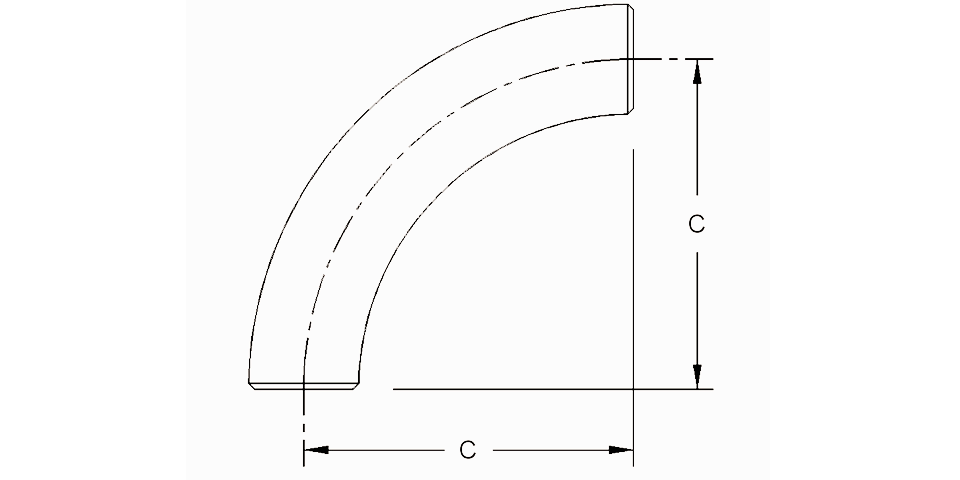
90° 3R – ANSI

Pipe Size (NPS)CApprox. Weight (lb)
STDXS
1/2 – – –
3/4 – – –
1 – – –
1 1/4 – – –
1 1/2 – – –
2 6 3.0 4.0
2 1/2 7 1/2 6.0 8.0
3 9 10.0 13.0
3 1/2 10 1/2 13.0 18.0
4 12 18.0 25.0
5 15 29.0 43.0
6 18 45.0 70.0
8 24 90.0 140.0
10 30 159.0 218.0
12 36 233.0 310.0
14 42 298.0 400.0
16 48 390.0 520.0
18 54 495.0 660.0
20 60 610.0 810.0
22 66 735.0 980.0
24 72 875.0 1170.0
  • Dimensions per ANSI/ASME B16.9.
  • A 90° elbow three radius is a long radius (LR) with the centerline curvature equal to 3 times the nominal pipe size (NPS).

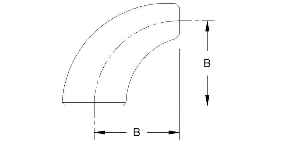
90° SR, Long Tangent ANSI

Pipe Size (NPS)ABCApprox. Weight (lb)
STDXS
1/2 – – – – –
3/4 – – – – –
1 – – – – –
1 1/4 – – – – –
1 1/2 – – – – –
2 – – – – –
2 1/2 – – – – –
3 – – – – –
3 1/2 – – – – –
4 – – – – –
5 – – – – –
6 – – – – –
8 10 2 8 41.0 63.0
10 12 1/2 2 1/2 10 74.0 100.0
12 15 3 12 109.0 142.0
14 17 1/2 3 1/2 14 140.0 189.0
16 20 4 16 172.0 241.0
18 22 1/2 4 1/2 18 218.0 305.0
20 25 5 20 275.0 387.0
22 30 6 24 390.0 546.0
24 32 6 26 460.0 620.0
  • Dimensions per ANSI/ASME B16.9.
  • A 90° elbow long tangent is a short radius (SR) with the centerline curvature equal to 1 times the nominal pipe size (NPS) and a straight extension at both ends (long tangent) for 8 inch and larger sizes. Tangent elbows provide a straight length at the end to accept a Slip-on Flange. The tangent end for the flange is not beveled.
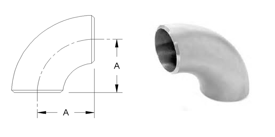
90° SR – ANSI

Pipe Size (NPS)AApprox. Weight (lb)
STDXS
1/2 – – –
3/4 – – –
1 1 0.3 0.3
1 1/4 1 1/4 0.4 0.5
1 1/2 1 1/2 0.6 0.8
2 2 1.0 1.5
2 1/2 2 1/2 2.1 2.8
3 3 3.0 4.3
3 1/2 3 1/2 4.5 6.0
4 4 6.3 8.5
5 5 9.6 14.0
6 6 18.0 23.0
8 8 34.0 47.5
10 10 58.0 70.0
12 12 80.0 104.0
14 14 105.0 140.0
16 16 132.0 174.0
18 18 167.0 219.0
20 20 210.0 275.0
22 22 256.0 338.0
24 24 298.0 398.0
  • A 90° elbow short radius (SR) has a centerline curvature equal to 1 times the nominal pipe size (NPS) for 1 inch and larger size
  • Dimensions are shown in inches and pounds per ANSI/ASME B16.9.

90° LR, Reduce, ANSI

Pipe Size (NPS)BApprox. Weight (lb)
STDXS
2 x 1-1/2 3 1.3 1.8
2 x 1-1/4 3 1.2 1.7
2 x 1 3 1.1 1.5
       
2-1/2 x 2 3 3/4 2.5 3.3
2-1/2 x 1-1/2 3 3/4 2.2 2.9
2-1/2 x 1-1/4 3 3/4 2.1 2.8
       
3 x 2-1/2 4 1/2 4.2 5.5
3 x 2 4 1/2 3.5 4.7
3 x 1-1/2 4 1/2 3.2 4.3
       
3-1/2 x 3 5 1/4 6.0 8.2
3-1/2 x 2-1/2 5 1/4 5.4 7.3
3-1/2 x 2 5 1/4 4.5 6.3
       
4 x 3-1/2 6 8.2 11.3
4 x 3 6 7.5 10.4
4 x 2-1/2 6 10.5 9.3
4 x 2 6 6.0 8.3
       
5 x 4 7 1/2 13.1 19.0
5 x 3-1/2 7 1/2 12.2 17.0
5 x 3 7 1/2 11.4 16.0
5 x 2-1/2 7 1/2 10.5 15.0
       
6 x 5 9 21.0 31.5
6 x 4 9 19.0 27.0
6 x 3-1/2 9 18.0 26.0
6 x 3 9 17.0 24.0
       
8 x 6 12 39.0 59.0
8 x 5 12 26.0 53.0
8 x 4 12 33.0 48.0
10 x 8 15 71.0 101.0
10 x 6 15 62.0 86.0
10 x 5 15 57.0 78.0
       
12 x 10 18 112.0 149.0
12 x 8 18 97.0 135.0
12 x 6 18 85.0 116.0
       
14 x 12 21 137.0 180.0
14 x 10 21 127.0 166.0
14 x 8 21 115.0 151.0
       
16 x 14 24 177.0 231.0
16 x 12 24 169.0 221.0
16 x 10 24 157.0 205.0
       
18 x 16 27 238.0 320.0
18 x 14 27 228.0 310.0
18 x 12 27 218.0 300.0
18 x 10 27 208.0 290.0
       
20 x 18 30 305.0 400.0
20 x 16 30 295.0 385.0
20 x 14 30 280.0 365.0
20 x 12 30 265.0 350.0
20 x 10 30 250.0 325.0
       
24 x 22 36 428.0 567.0
24 x 20 36 410.0 544.0
24 x 18 36 395.0 523.0
24 x 16 36 376.0 499.0
24 x 14 36 362.0 480.0
24 x 12 36 353.0 466.0
  • Dimensions per ANSI/ASME B16.9.
  • A better flow efficiency is achieved using a reducing 90° than using a 90° and a concentric reducer. Also you have one less weld.
error: Copy is disabled