Showing posts with tag: Imperial
Jan 17, 2018
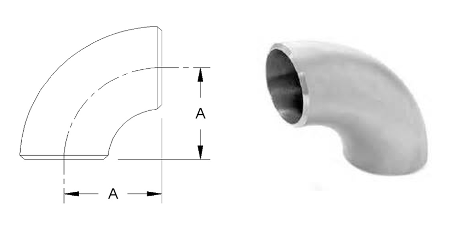
Pipe Size (NPS) A Approx. Weight (lb) STD XS
1/2
–
–
–
3/4
–
–
–
1
1
0.3
0.3
1 1/4
1 1/4
0.4
0.5
1 1/2
1 1/2
0.6
0.8
2
2
1.0
1.5
2 1/2
2 1/2
2.1
2.8
3
3
3.0
4.3
3 1/2
3 1/2
4.5
6.0
4
4
6.3
8.5
5
5
9.6
14.0
6
6
18.0
23.0
8
8
34.0
47.5
10
10
58.0
70.0
12
12
80.0
104.0
14
14
105.0
140.0
16
16
132.0
174.0
18
18
167.0
219.0
20
20
210.0
275.0
22
22
256.0
338.0
24
24
298.0
398.0
A 90° elbow short radius (SR) has a centerline curvature equal to 1 times the nominal pipe size (NPS) for 1 inch and larger size
Dimensions are shown in inches and pounds per ANSI/ASME B16.9.
Jan 17, 2018
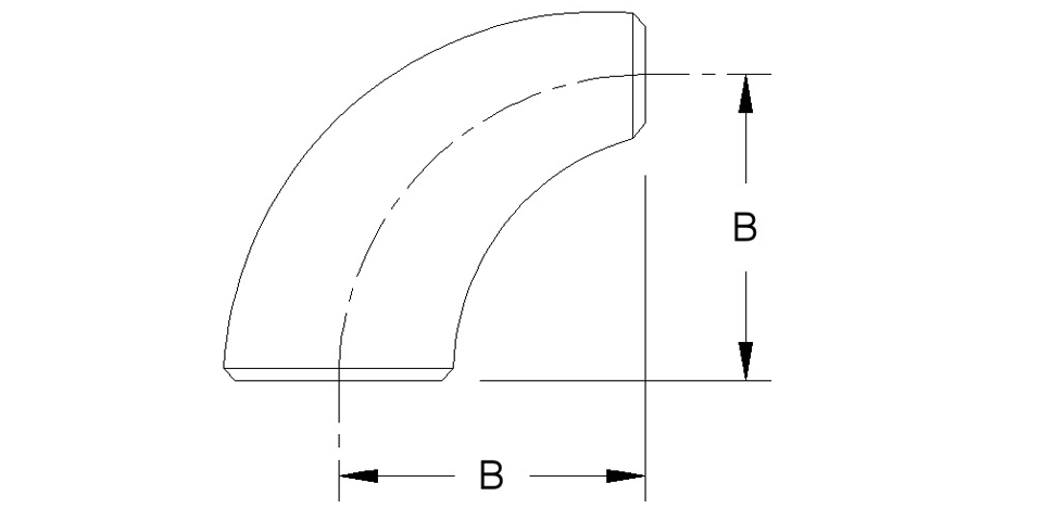
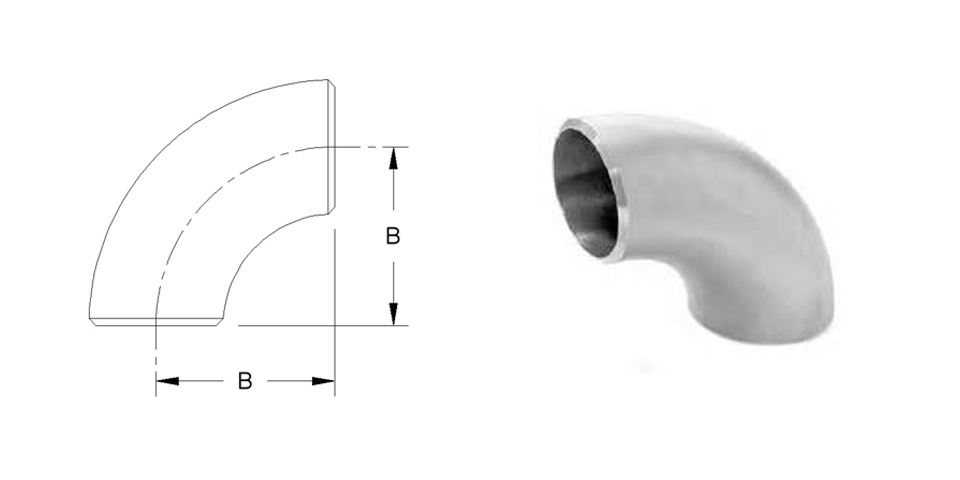
Pipe Size (NPS) B Approx. Weight (lb) STD XS
2 x 1-1/2
3
1.3
1.8
2 x 1-1/4
3
1.2
1.7
2 x 1
3
1.1
1.5
2-1/2 x 2
3 3/4
2.5
3.3
2-1/2 x 1-1/2
3 3/4
2.2
2.9
2-1/2 x 1-1/4
3 3/4
2.1
2.8
3 x 2-1/2
4 1/2
4.2
5.5
3 x 2
4 1/2
3.5
4.7
3 x 1-1/2
4 1/2
3.2
4.3
3-1/2 x 3
5 1/4
6.0
8.2
3-1/2 x 2-1/2
5 1/4
5.4
7.3
3-1/2 x 2
5 1/4
4.5
6.3
4 x 3-1/2
6
8.2
11.3
4 x 3
6
7.5
10.4
4 x 2-1/2
6
10.5
9.3
4 x 2
6
6.0
8.3
5 x 4
7 1/2
13.1
19.0
5 x 3-1/2
7 1/2
12.2
17.0
5 x 3
7 1/2
11.4
16.0
5 x 2-1/2
7 1/2
10.5
15.0
6 x 5
9
21.0
31.5
6 x 4
9
19.0
27.0
6 x 3-1/2
9
18.0
26.0
6 x 3
9
17.0
24.0
8 x 6
12
39.0
59.0
8 x 5
12
26.0
53.0
8 x 4
12
33.0
48.0
10 x 8
15
71.0
101.0
10 x 6
15
62.0
86.0
10 x 5
15
57.0
78.0
12 x 10
18
112.0
149.0
12 x 8
18
97.0
135.0
12 x 6
18
85.0
116.0
14 x 12
21
137.0
180.0
14 x 10
21
127.0
166.0
14 x 8
21
115.0
151.0
16 x 14
24
177.0
231.0
16 x 12
24
169.0
221.0
16 x 10
24
157.0
205.0
18 x 16
27
238.0
320.0
18 x 14
27
228.0
310.0
18 x 12
27
218.0
300.0
18 x 10
27
208.0
290.0
20 x 18
30
305.0
400.0
20 x 16
30
295.0
385.0
20 x 14
30
280.0
365.0
20 x 12
30
265.0
350.0
20 x 10
30
250.0
325.0
24 x 22
36
428.0
567.0
24 x 20
36
410.0
544.0
24 x 18
36
395.0
523.0
24 x 16
36
376.0
499.0
24 x 14
36
362.0
480.0
24 x 12
36
353.0
466.0
Dimensions per ANSI/ASME B16.9.
A better flow efficiency is achieved using a reducing 90° than using a 90° and a concentric reducer. Also you have one less weld.
Jan 17, 2018
Pipe Size (NPS) A B C Approx. Weight (lb) STD XS
1/2
–
–
–
–
–
3/4
–
–
–
–
–
1
–
–
–
–
–
1 1/4
–
–
–
–
–
1 1/2
–
–
–
–
–
2
3 1/2
1/2
3
1.8
2.5
2 1/2
4 3/8
5/8
3 3/4
3.8
5.0
3
5 1/4
3/4
4 1/2
5.8
8.0
3 1/2
6 1/8
7/8
5 1/4
7.7
11.0
4
7
1
6
11.0
15.0
5
8 3/4
1 1/4
7 1/2
17.0
25.0
6
10 1/2
1 1/2
9
29.0
45.0
8
14
2
12
55.0
85.0
10
17 1/2
2 1/2
15
95.0
130.0
12
21
3
18
146.0
195.0
14
24 1/2
3 1/2
21
185.0
245.0
16
28
4
24
246.0
329.0
18
31 1/2
4 1/2
27
316.0
420.0
20
35
5
30
400.0
475.0
22
38 1/2
5 1/2
33
468.0
625.0
24
42
6
36
571.0
750.0
Dimensions per ANSI/ASME B16.9.
A 90° elbow long tangent is a long radius (LR) with the centerline curvature equal to 1-1/2 times the nominal pipe size (NPS) and a straight extension at both ends (long tangent) for 2 inch and larger sizes. Tangent elbows provide a straight length at the end to accept a Slip-on Flange. The tangent end for the flange is not beveled.
Jan 17, 2018
Pipe Size (NPS) B Approx. Weight (lb) STD XS XXS
1/2
1 1/2
0.2
0.3
–
3/4
1 1/2
0.2
0.3
–
1
1 1/2
0.4
0.5
0.8
1 1/4
1 7/8
0.6
0.9
1.4
1 1/2
2 1/4
0.9
1.2
1.5
2
3
1.6
2.2
3.5
2 1/2
3 3/4
3.3
4.0
7.0
3
4 1/2
5.0
6.5
11.0
3 1/2
5 1/4
6.8
8.4
16.0
4
6
9.0
13.5
20.0
5
7 1/2
15.5
22.0
36.0
6
9
24.5
35.0
65.0
8
12
50.0
71.0
118.0
10
15
88.0
107.0
–
12
18
125.0
160.0
–
14
21
160.0
205.0
–
16
24
206.0
276.0
–
18
27
260.0
340.0
–
20
30
320.0
420.0
–
22
33
394.0
520.0
–
24
36
460.0
600.0
–
Dimensions per ANSI/ASME B16.9.
A 90° elbow long radius (LR) has a centerline curvature equal to 1-1/2 times the nominal pipe size (NPS) for 3/4 inch and larger sizes.
Jan 17, 2018
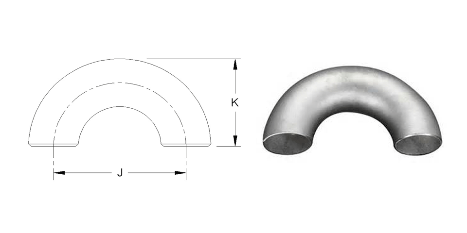
Pipe Size (NPS) J K Approx. Weight (lb) STD XS XXS
1/2
3
1 15/16
0.4
–
–
3/4
2 1/4
1 11/16
0.4
0.7
–
1
3
2 3/16
0.8
1.0
1.5
1 1/4
3 3/4
2 3/4
1.3
1.8
2.7
1 1/2
4 1/2
3 1/4
1.9
2.4
4.0
2
6
4 3/16
3.2
4.4
7.5
2 1/2
7 1/2
5 3/16
6.5
8.0
14.0
3
9
6 1/4
10.3
13.0
22.0
3 1/2
10 1/2
7 1/4
13.0
16.8
32.0
4
12
8 1/4
18.5
25.0
40.0
5
15
10 5/16
30.0
44.0
72.0
6
18
12 5/16
50.0
70.0
130.0
8
24
16 5/16
95.0
142.0
236.0
10
30
20 3/8
117.0
215.0
–
12
36
24 3/8
230.0
320.0
–
14
42
28
325.0
400.0
–
16
48
32
412.0
550.0
–
18
54
36
510.0
690.0
–
20
60
40
640.0
830.0
–
22
66
44
787.0
1040.0
–
24
72
48
890.0
1200.0
–
Dimensions per ANSI/ASME B16.9.
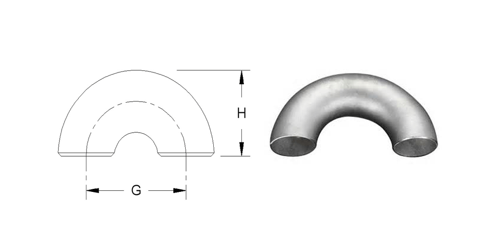
A 180° return long radius (LR) has a centerline curvature equal to 1-1/2 times the nominal pipe size (NPS) for 3/4 inch and larger sizes.
Jan 17, 2018
Pipe Size (NPS) G H Approx. Weight (lb) STD XS
1/2
–
–
–
–
3/4
–
–
–
–
1
2
1 5/8
0.5
–
1 1/4
2 1/2
2 1/16
0.8
–
1 1/2
3
2 7/16
1.2
1.5
2
4
3 3/16
2.0
3.0
2 1/2
5
3 15/16
4.3
5.6
3
6
4 3/4
6.0
8.5
3 1/2
7
5 1/2
9.0
12.0
4
8
6 1/4
12.5
17.0
5
10
7 3/4
19.0
28.0
6
12
9 5/16
35.0
46.0
8
16
12 5/16
68.0
100.0
10
20
15 3/8
115.0
140.0
12
24
18 3/8
155.0
218.0
14
28
21
210.0
275.0
16
32
24
260.0
340.0
18
36
27
330.0
430.0
20
40
30
410.0
550.0
22
–
–
–
–
24
48
36
590.0
780.0
Dimensions per ANSI/ASME B16.9.
A 180° return short radius (SR) has a centerline curvature equal to 1 times the nominal pipe size (NPS) for 1 inch and larger sizes.
Jan 17, 2018
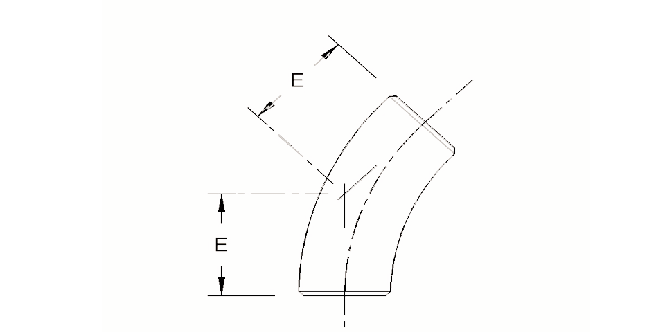
Pipe Size (NPS) E Approx. Weight (lb) STD XS
1/2
–
–
–
3/4
–
–
–
1
–
–
–
1 1/4
–
–
–
1 1/2
–
–
–
2
2 1/2
1.5
2.1
2 1/2
3 1/8
3.0
4.0
3
3 3/4
5.0
7.0
3 1/2
–
–
–
4
5
9.0
13.0
5
–
–
–
6
7 1/2
23.0
35.0
8
10
45.0
70.0
10
12 1/2
80.0
109.0
12
14 7/8
117.0
155.0
14
17 3/8
149.0
200.0
16
19 7/8
195.0
260.0
18
22 3/8
248.0
330.0
20
24 7/8
305.0
405.0
22
27 1/4
368.0
490.0
24
29 3/4
438.0
585.0
Dimensions per ANSI/ASME B16.9.
A 45° elbow three radius is a long radius (LR) with the centerline curvature equal to 3 times the nominal pipe size (NPS).
Jan 16, 2018
Pipe Size (NPS) A B Approx. Weight (lb) STD XS
1/2
–
–
–
–
3/4
–
–
–
–
1
–
–
–
–
1 1/4
–
–
–
–
1 1/2
–
–
–
–
2
1 7/8
1/2
1.0
1.5
2 1/2
2 3/8
5/8
2.0
2.8
3
2 3/4
3/4
3.2
4.2
3 1/2
3 1/8
7/8
4.8
6.5
4
3 1/2
1
6.2
8.5
5
4 3/8
1 1/4
10.0
14.0
6
5 1/4
1 1/2
15.0
24.0
8
7
2
31.0
48.0
10
8 3/4
2 1/2
58.0
79.0
12
10 1/2
3
84.0
112.0
14
12 1/4
3 1/2
111.0
142.0
16
14
4
145.0
186.0
18
15 3/4
4 1/2
185.0
242.0
20
17 1/2
5
226.0
297.0
22
–
–
–
–
24
21
6
333.0
428.0
Dimensions per ANSI/ASME B16.9.
A 45° elbow long tangent is a long radius (LR) with the centerline curvature equal to 1-1/2 times the nominal pipe size (NPS) and a straight extension at both ends (long tangent) for 2 inch and larger sizes. Tangent elbows provide a straight length at the end to accept a Slip-on Flange. The tangent end for the flange is not beveled.
Jan 16, 2018
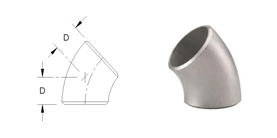
Pipe Size (NPS) D Approx. Weight (lb) STD XS XXS
1/2
5/8
0.1
0.2
–
3/4
3/4
0.1
0.2
–
1
7/8
0.3
0.3
0.4
1 1/4
1
0.4
0.5
0.8
1 1/2
1 1/8
0.4
0.7
1.1
2
1 3/8
0.8
1.2
2.0
2 1/2
1 3/4
1.8
2.1
3.8
3
2
2.6
3.5
5.8
3 1/2
2 1/4
3.5
4.5
8.5
4
2 1/2
4.5
6.1
11
5
3 1/8
7.5
11
19.0
6
3 3/4
12.0
18
32.0
8
5
23.0
35.0
60.0
10
6 1/4
43.0
53.0
–
12
7 1/2
62.0
84.0
–
14
8 3/4
80.0
100.0
–
16
10
100.0
135.0
–
18
11 1/4
126.0
167.0
–
20
12 1/2
160.0
206.0
–
22
13 1/2
197.0
260.0
–
24
15
238.0
300.0
–
Dimensions are listded in inches and millimeters per ANSI/ASME B16.9.
A 45° elbow long radius (LR) has a centerline curvature equal to 1-1/2 times the nominal pipe size (NPS) for 3/4 inch and larger sizes.
Jan 16, 2018
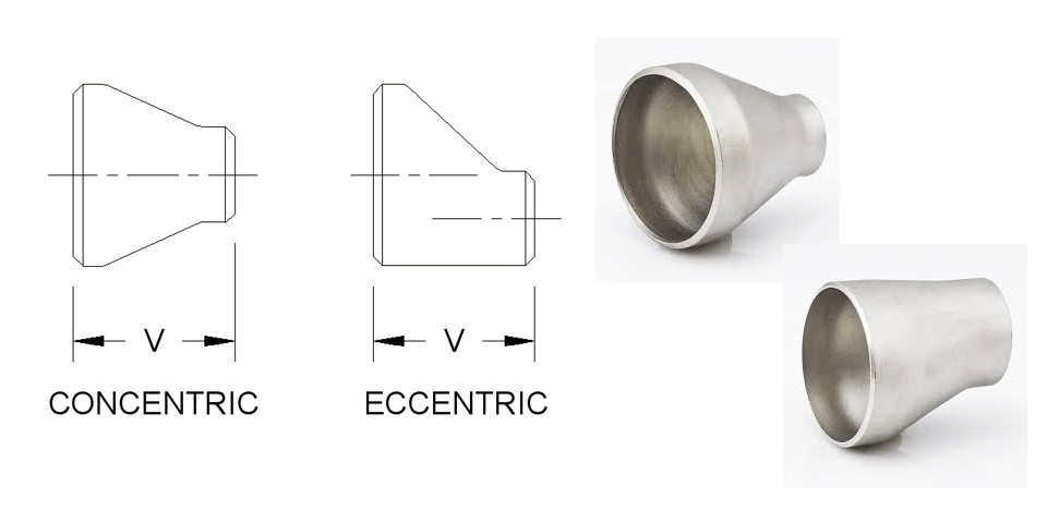
Pipe Size (NPS) V Approx. Weight (lb) STD XS
3/4 x 1/2
1 1/2
0.2
0.3
3/4 x 3/8
1 1/2
0.2
0.3
1 x 3/4
2
0.3
0.4
1 x 1/2
2
0.3
0.4
1 x 3/8
2
0.3
0.4
1 1/4 x 1
2
0.5
0.6
1 1/4 x 3/4
2
0.5
0.5
1 1/4 x 1/2
2
0.5
0.5
1 1/2 x 1 1/4
2 1/2
0.6
0.8
1 1/2 x 1
2 1/2
0.6
0.7
1 1/2 x 3/4
2 1/2
0.5
0.6
1 1/2 x 1/2
2 1/2
0.5
0.6
2 x 1 1/2
3
0.9
1.2
2 x 1 1/4
3
0.9
1.1
2 x 1
3
0.9
1.0
2 x 3/4
3
0.8
1.0
2 1/2 x 2
3 1/2
1.6
2.0
2 1/2 x 1 1/2
3 1/2
1.5
1.8
2 1/2 x 1 1/4
3 1/2
1.4
1.7
2 1/2 x 1
3 1/2
1.3
1.7
3 x 2 1/2
3 1/2
2.1
2.8
3 x 2
3 1/2
2.0
2.6
3 x 1 1/2
3 1/2
1.8
2.1
3 x 1 1/4
3 1/2
1.7
2.2
3 x 1
3 1/2
1.6
2.0
3 1/2 x 3
4
3.0
4.0
3 1/2 x 2 1/2
4
2.9
3.8
3 1/2 x 2
4
2.7
3.5
3 1/2 x 1 1/2
4
2.5
3.1
3 1/2 x 1 1/4
4
2.3
3.2
4 x 3 1/2
4
3.6
4.8
4 x 3
4
3.5
4.7
4 x 2 1/2
4
3.3
4.4
4 x 2
4
3.1
3.9
4 x 1 1/2
4
2.7
3.8
4 x 1 1/4
4
2.6
3.5
4 x 1
4
2.4
3.3
5 x 4
5
5.9
8.3
5 x 3 1/2
5
5.8
8.0
5 x 3
5
5.7
7.8
5 x 2 1/2
5
5.5
7.2
5 x 2
5
5.0
6.6
5 x 1 1/2
5
4.8
6.2
6 x 5
5 1/2
8.6
12.6
6 x 4
5 1/2
8.1
12.0
6 x 3 1/2
5 1/2
8.1
11.6
6 x 3
5 1/2
8.0
11.1
6 x 2 1/2
5 1/2
7.6
9.9
6 x 2
5 1/2
6.9
9.0
8 x 6
6
13.9
20.4
8 x 5
6
13.4
19.5
8 x 4
6
13.1
18.6
8 x 3 1/2
6
12.8
16.1
8 x 3
6
12.4
15.5
10 x 8
7
23.2
31.4
10 x 6
7
22.3
29.8
10 x 5
7
21.8
28.7
10 x 4
7
21.1
25.3
10 x 3
7
20.6
23.2
12 x 10
8
33.4
43.6
12 x 8
8
32.1
37.4
12 x 6
8
31.1
40.6
12 x 5
8
30.5
39.1
12 x 4
8
29.2
38.6
14 x 12
13
63.0
83.0
14 x 10
13
60.0
79.0
14 x 8
13
57.0
76.0
14 x 6
13
55.0
74.0
16 x 14
14
77.0
102.0
16 x 12
14
75.0
99.0
16 x 10
14
72.0
96.0
16 x 8
14
70.0
93.0
16 x 6
14
67.0
91.0
18 x 16
15
94.0
123.0
18 x 14
15
90.0
120.0
18 x 12
15
89.0
118.0
18 x 10
15
86.0
114.0
18 x 8
15
82.0
109.0
20 x 18
20
142.0
186.0
20 x 16
20
138.0
182.0
20 x 14
20
135.0
179.0
20 x 12
20
134.0
176.0
20 x 10
20
132.0
172.0
22 x 20
20
157.0
207.0
22 x 18
20
154.0
202.0
22 x 16
20
151.0
198.0
22 x 14
20
148.0
195.0
22 x 12
20
145.0
182.0
22 x 10
20
141.0
178.0
24 x 20
20
167.0
220.0
24 x 18
20
163.0
215.0
24 x 16
20
160.0
211.0
24 x 14
20
158.0
209.0
24 x 12
20
156.0
206.0
24 x 10
20
153.0
202.0
Dimensions per ANSI/ASME B16.9.
The concentric reducer centerline of the inlet and outlet is at the same level.
The eccentric reducer offset is equals 1/2 times the larger ID minus the smaller ID.