The drill size chart provides a list of standard size drill bits in several measurement systems, including fractional, metric, wire gauge number, and letter.
The decimal equivalents of the diameters are shown in both English and Metric units.
Fractional sizes are measured in inches, while metric sizes are measured in millimeters.
The wire gauge and letter systems refer to tool diameters that increase as the wire gauge decreases from #107 to #1 and then continues from A to Z.
The drill size chart contains tools up to 1.5 inches in diameter, but larger tools are also commonly used.
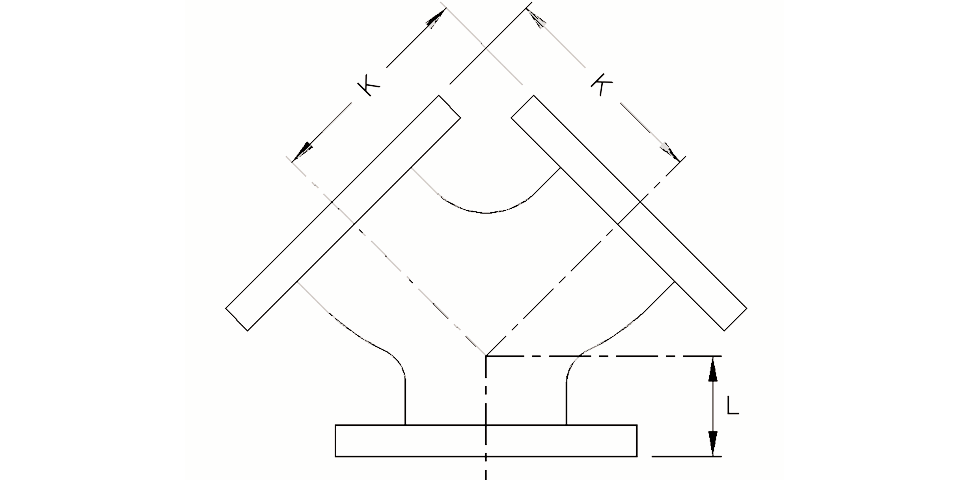
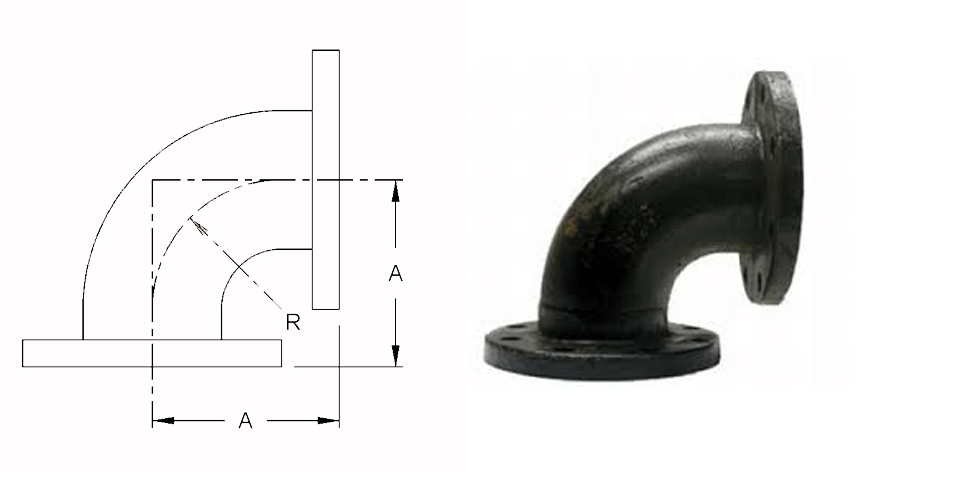
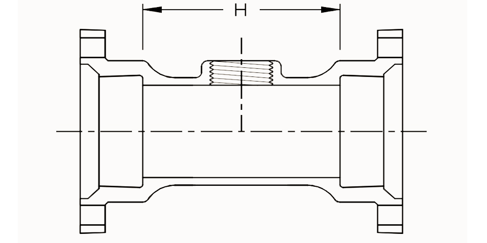
AWWA C110/A21.10 – Ductile-Iron and Gray-Iron Fittings (3″ to 48″)
AWWA C104/A21.4 – Standard for Cement-Mortar Lining for Ductile-Iron Pipe and Fittings for Water
ASME B16.1 – Gray Iron Pipe Flanges and Flanged Fittings: Classes 25, 125, and 250 (Flange surfaces shall be faced and drilled in accordance with ANSI Class 125)
All ductile iron flanged fittings shall be rated for water pressure of 250 PSI.
Flanged ductile iron fittings in 24 inch and smaller sizes may be rated for 350 psi with the use of special gaskets.
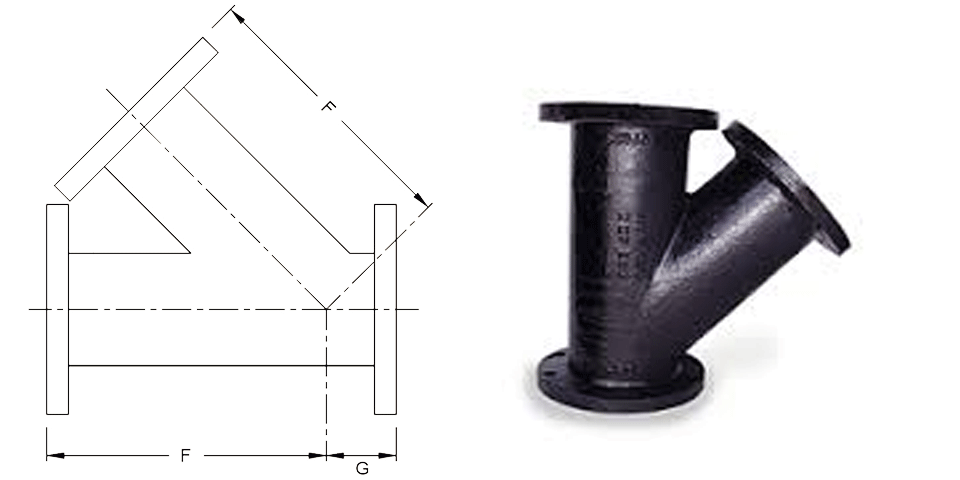
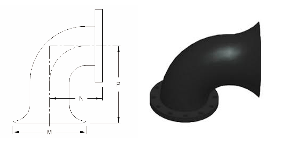
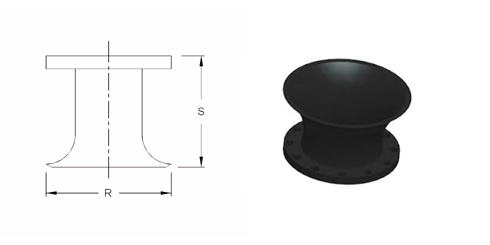
AWWA C110/A21.10 – Ductile-Iron and Gray-Iron Fittings (3″ to 48″)
ASME B16.1 – Gray Iron Pipe Flanges and Flanged Fittings: Classes 25, 125, and 250 (Flange surfaces shall be faced and drilled in accordance with ANSI Class 125)
AWWA C104/A21.4 – Standard for Cement-Mortar Lining for Ductile-Iron Pipe and Fittings for Water
AWWA C111/A21.11 – Rubber-Gasket Joints for Ductile-Iron Pressure Pipe and Fittings
Ductile iron mechanical joint fittings 3″ through 24″ shall be rated for 350 PSI working pressure.
Flanged ductile iron fittings in 24 inch and smaller sizes may be rated for 350 psi with the use of special gaskets.